Why does my DXF have open contours or “open entities”?
Updated Nov 11, 2026
Short answer: The outline is made of separate lines and arcs with tiny gaps between them. Join them into one closed outline before cutting or ordering.
Updated Nov 11, 2026
Short answer: The outline is made of separate lines and arcs with tiny gaps between them. Join them into one closed outline before cutting or ordering.
Drop your SVG or DXF file here
or
Free. Nothing is uploaded: the check runs on your own computer.
Marks: open ends cut twice dots and tiny bits text and pictures
Changing these checks the file again.
A plasma table or a metal shop's laser needs every part outline to be one closed loop. A DXF often breaks that rule without showing it:
SheetCAM shows these as open paths, other CAM software won't make a toolpath, and online metal shops ask you to fix the file.
By hand: in most CAD programs, select the outline and use Join (or PEDIT › Join in AutoCAD-style programs). If it will not join, there is a gap: zoom in on each corner.
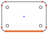
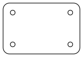
Download: before (DXF) · after (DXF)
It means a cut outline does not close: somewhere the line stops instead of meeting its start. Metal-cutting software cannot tell the inside of the part from the outside, so it will not make a toolpath, and online metal shops send the file back.
Corners can hide gaps of a thousandth of an inch. And many programs save an outline as separate lines and arcs that only touch at their ends. Most CAM software needs them joined, or within a small tolerance.
No. It joins and closes gaps up to 0.5 mm (you can raise this to 5 mm under More settings). A bigger gap usually means part of the outline is missing, which only you can redraw.
No. Langmuir says FireControl loads G-code. You turn the DXF into G-code in SheetCAM or Fusion first. A clean, closed DXF makes that step work.